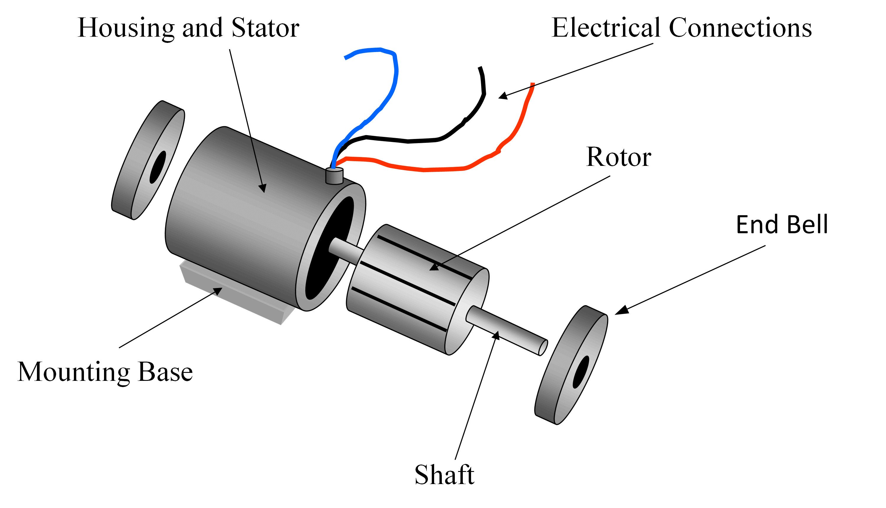
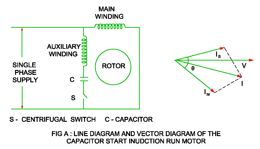
Ever wondered how the machines that power our world actually work? From industrial pumps to household appliances, the ubiquitous 3-phase induction motor is a silent workhorse. Understanding the blueprint of this powerful machine, its schematic diagram, is key to unlocking its secrets and harnessing its full potential.
A schematic diagram of a 3-phase induction motor is essentially a visual representation of its internal workings. It’s a roadmap that illustrates the connections between various components, including the stator windings, rotor, and power supply. This graphical representation is crucial for anyone working with these motors, whether you're an engineer designing a new system or a technician troubleshooting a malfunctioning machine.
Think of it like the nervous system of the motor, showing how electrical energy is transformed into mechanical power. By understanding this visual language, we can diagnose issues, optimize performance, and even design new, more efficient motor systems. This seemingly complex diagram is actually a powerful tool, simplifying the complexities of the motor's operation.
The historical development of these diagrams mirrors the evolution of the motor itself. Early diagrams were simple, reflecting the rudimentary understanding of electromagnetism. As technology advanced, so too did the diagrams, incorporating more details and becoming increasingly standardized. Today, these diagrams are essential for communication among engineers and technicians worldwide.
These diagrams are not merely historical artifacts; they are vital tools in modern industry. They provide a common language for engineers and technicians, allowing them to communicate effectively about the design, installation, and maintenance of these motors. A clear understanding of a motor's wiring diagram can prevent costly mistakes and ensure the safe and efficient operation of critical equipment.
A 3-phase induction motor wiring representation illustrates the interconnection of the three phases of the power supply to the stator windings. These windings create a rotating magnetic field that interacts with the rotor, causing it to spin. A simplified representation might show the three phases labeled as L1, L2, and L3, connected to the corresponding stator windings.
Benefits of understanding these diagrams are threefold. First, they enable effective troubleshooting. By tracing the circuit paths on the diagram, technicians can quickly identify faulty components or wiring errors. Second, they aid in system design. Engineers use these diagrams to ensure proper integration of the motor into larger systems. Finally, they facilitate maintenance. Diagrams guide technicians during routine inspections and repairs, ensuring the motor's long-term reliability.
For example, a technician might use a diagram to identify a blown fuse or a broken connection within the motor. An engineer might utilize a diagram to determine the appropriate starting method for a large industrial motor. And a maintenance worker might refer to a diagram to ensure the correct wiring configuration after replacing a damaged component.
Advantages and Disadvantages of Using Schematic Diagrams
| Advantages | Disadvantages |
|---|---|
| Simplified understanding of complex systems | Can be overwhelming for beginners |
| Facilitates troubleshooting and repairs | Requires basic electrical knowledge to interpret |
| Aids in system design and integration | May not reflect all the physical details of the motor |
Best practices for utilizing these diagrams include: ensuring you have the correct diagram for the specific motor model, understanding the symbols and conventions used in the diagram, and using a multimeter to verify the connections shown in the diagram. Always double-check your work and consult with experienced professionals if you're unsure about any aspect of the diagram.
Real-world applications abound, from powering conveyor belts in factories to driving pumps in water treatment plants. Understanding the schematic diagram is crucial in all these applications for ensuring optimal performance and reliability.
Frequently asked questions often revolve around interpreting specific symbols, understanding the different types of connections, and troubleshooting common problems. Resources like online forums, textbooks, and manufacturer's manuals can provide valuable insights.
Tips and tricks for understanding diagrams more effectively include studying basic electrical principles, practicing reading diagrams of simpler circuits, and seeking guidance from experienced professionals. The more you practice, the more comfortable you'll become with interpreting these essential tools.
In conclusion, the schematic diagram of a 3-phase induction motor is an invaluable tool for anyone working with these essential machines. It's a visual language that unlocks the inner workings of the motor, allowing us to understand its operation, diagnose problems, and optimize performance. From the simplest pump to the most complex industrial machinery, understanding these diagrams is essential for ensuring the smooth and efficient operation of our electrified world. Embrace the power of the schematic and unlock the full potential of the 3-phase induction motor. Take the time to study and understand these diagrams, and you'll be well-equipped to tackle any challenge related to these powerful machines. The knowledge gained will empower you to maintain, troubleshoot, and even design systems that utilize these essential components of modern industry.
Decoding the secrets of the current transformer symbol iec
Streamlining project completion mastering the contoh surat permohonan opname pekerjaan
Navigating financial landscapes great plains bank in moore
3 phase DOL starter control circuit diagram working principle - You're The Only One I've Told
Three Phase Induction Motor Circuit Diagram - You're The Only One I've Told
Schematic Diagram Of Induction Motor - You're The Only One I've Told
Start And Run Capacitor Wiring - You're The Only One I've Told
Pwm Motor Driver Circuit - You're The Only One I've Told
Induction Motor All Parts Name at Robert Tompkins blog - You're The Only One I've Told
Forward Reverse Motor Control Diagram For 3 Phase Motor - You're The Only One I've Told
Three Phase Induction Motor Types Working and Applications - You're The Only One I've Told
3 Phase Motor Control Circuit Diagram - You're The Only One I've Told
Control Circuit Wiring Diagrams - You're The Only One I've Told
DIAGRAM Wiring Diagram Of Three Phase Induction Motor - You're The Only One I've Told
Start And Run Capacitors For Electric Motors - You're The Only One I've Told
3 Phase Wiring Circuit Diagram - You're The Only One I've Told
3 Phase Motor To Single Phase Wiring Diagram - You're The Only One I've Told
3 Phase Induction Motor Circuit Diagram - You're The Only One I've Told


