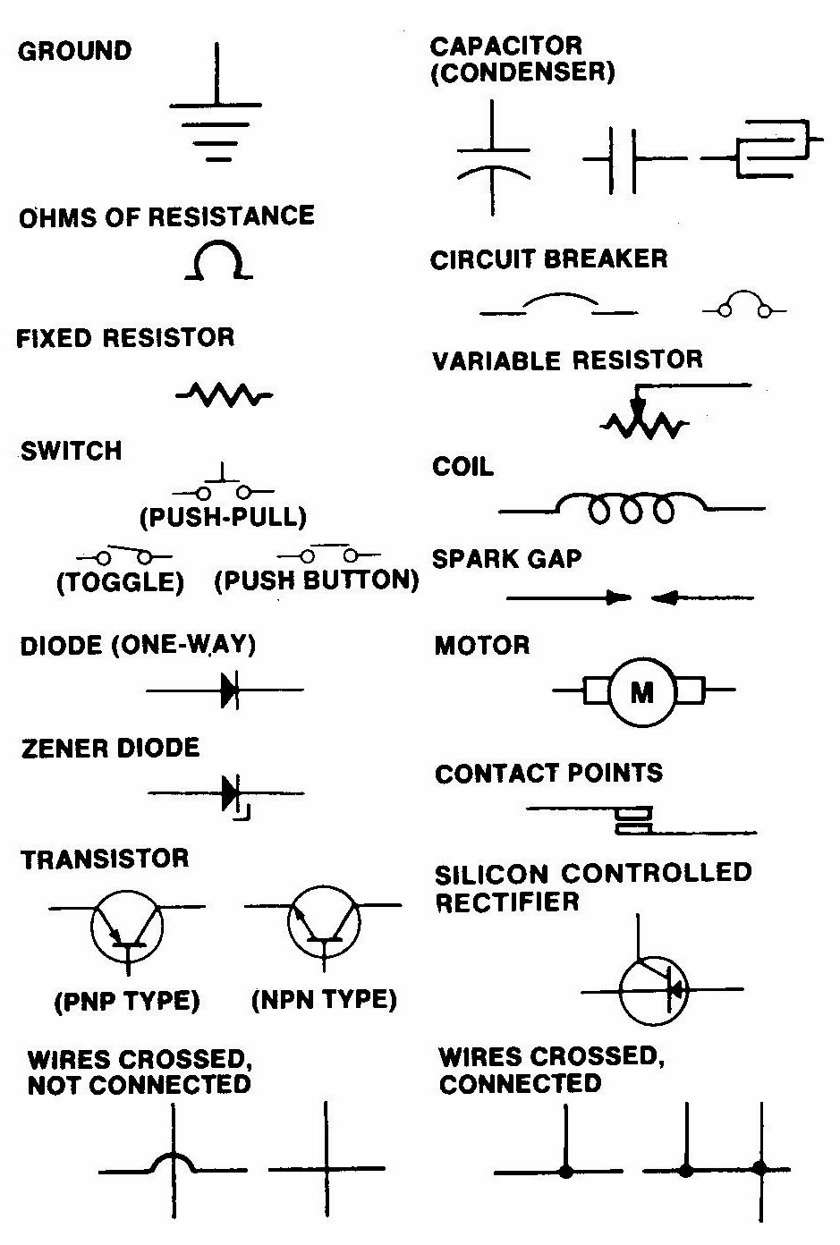
Ever looked at an electrical schematic and felt like you were deciphering an ancient language? You're not alone. Electrical schematics are the roadmaps of circuits, and their common symbols are the language they're written in. Understanding these symbols is crucial for anyone working with electronics, from seasoned engineers to DIY enthusiasts.
These graphical representations convey complex electrical connections and components in a concise and standardized way. Imagine trying to describe a complex circuit with just words – it would be a confusing mess. Schematic symbols provide a visual shorthand, allowing engineers and technicians to communicate and understand circuit designs quickly and efficiently.
The history of electrical schematic symbols traces back to the early days of electrical engineering. As circuits became more complex, the need for a standardized visual language became apparent. Over time, these symbols evolved, becoming more refined and standardized by organizations like the IEEE (Institute of Electrical and Electronics Engineers) and IEC (International Electrotechnical Commission).
The importance of these symbols lies in their ability to facilitate clear communication. They eliminate ambiguity and ensure that everyone involved in a project is on the same page. Misinterpreting a symbol can lead to costly errors, malfunctioning circuits, or even safety hazards. Therefore, accurate interpretation and use of these schematic representations are paramount.
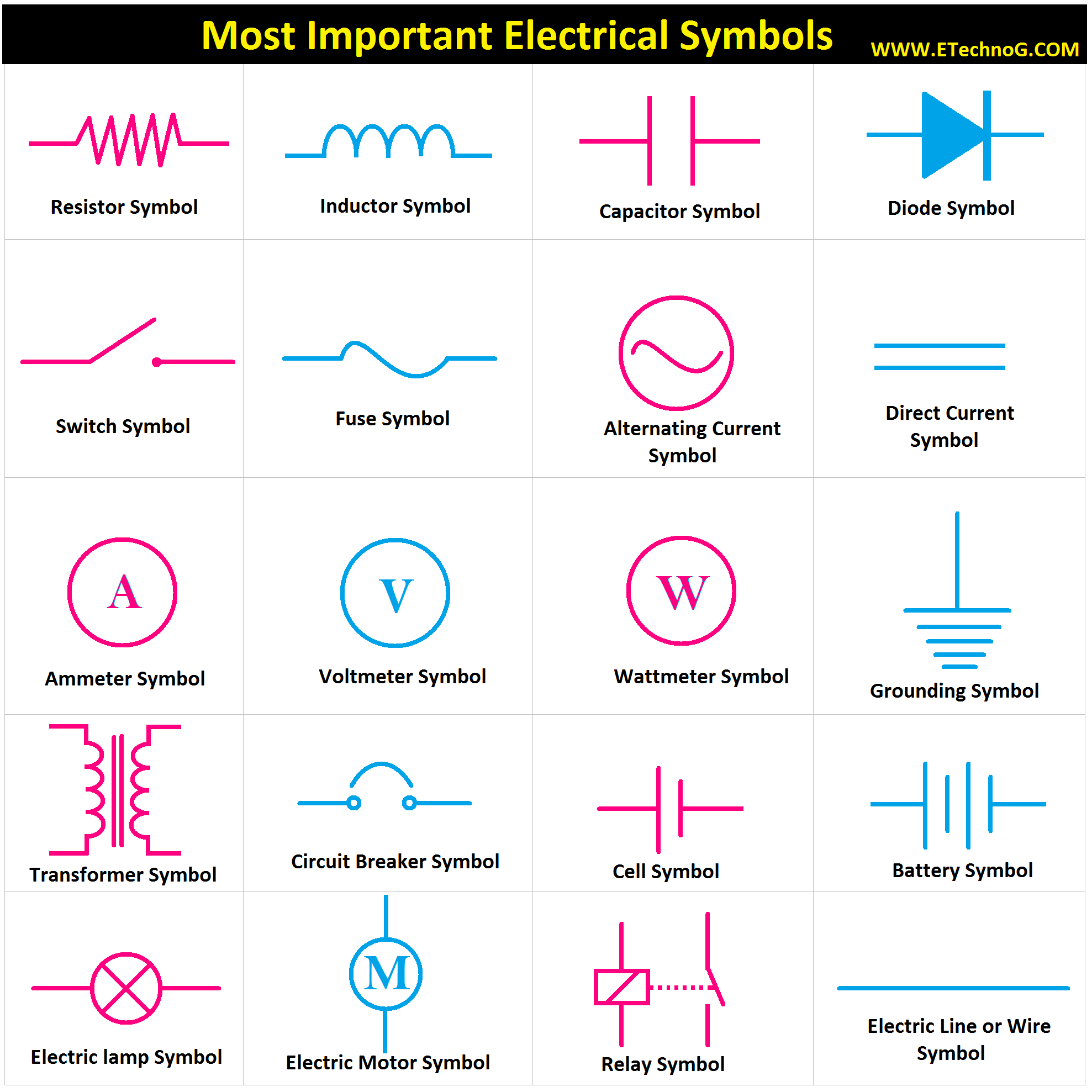
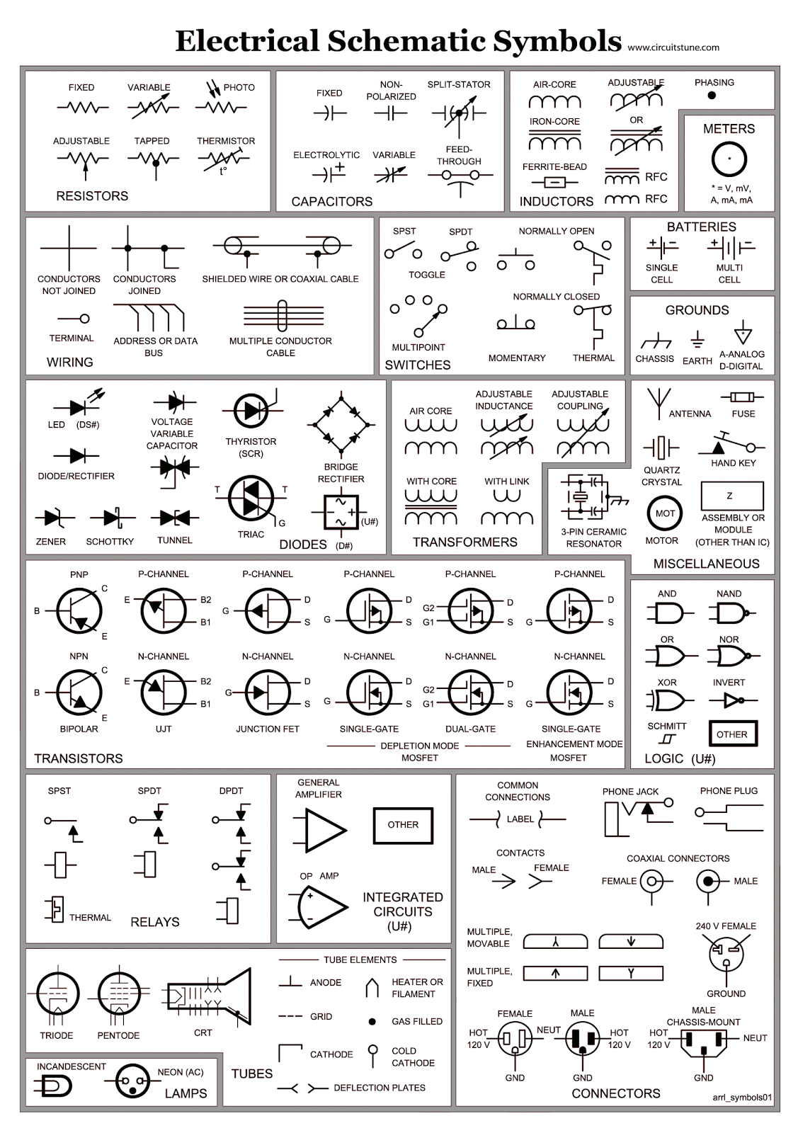
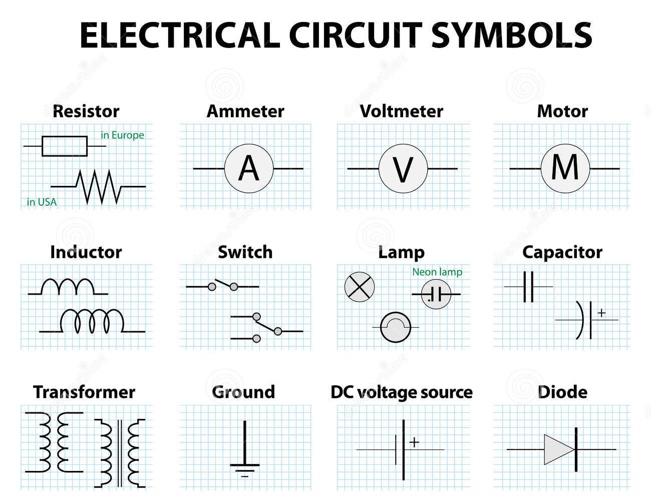
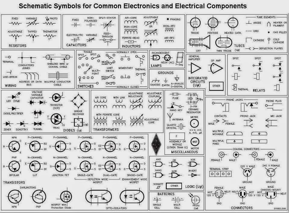
A key issue related to schematic symbols is the potential for confusion if one isn't familiar with the standards. Different standards may use slightly different symbols for the same component, making it crucial to understand which standard is being used in a particular schematic diagram. For instance, the symbol for a resistor may differ slightly between American and European standards.
A simple example is the symbol for a battery, represented by two parallel lines, one longer than the other. The longer line represents the positive terminal, while the shorter line signifies the negative terminal. This simple symbol clearly communicates the presence and polarity of a power source within the circuit.
One benefit of using standardized symbols is improved communication among engineers and technicians. Another advantage is enhanced troubleshooting. Standardized symbols make it easier to identify and isolate faulty components in a circuit. Lastly, using standard symbols allows for efficient circuit design and analysis, enabling engineers to simulate and optimize circuit performance before physical implementation.
Creating an action plan for learning schematic symbols involves identifying the relevant standards for your field, utilizing resources like textbooks and online tutorials, and practicing reading and interpreting diagrams. A successful example would be designing a simple circuit, such as a light switch circuit, using the appropriate symbols and then building the physical circuit based on the schematic.
Advantages and Disadvantages of Standardized Electrical Schematic Symbols
| Advantages | Disadvantages |
|---|---|
| Clear and concise communication | Requires learning and memorization of symbols |
| Facilitates troubleshooting | Potential for confusion between different standards |
| Enables efficient circuit design | Can be complex for highly intricate circuits |
Best practices include adhering to recognized standards, using clear and consistent labeling, and maintaining neat and organized diagrams. Ensuring proper spacing and alignment of symbols improves readability, while adding annotations and comments can provide valuable context.
One real-world example of schematic symbols in action is in the automotive industry, where complex wiring diagrams utilize these symbols to illustrate the intricate electrical systems of vehicles. Another is in building construction, where electrical plans use schematic symbols to guide electricians during installation.
A common challenge is keeping up with evolving standards. The solution is continuous learning and staying informed about updates. Another challenge is the sheer number of symbols. A solution is to focus on learning the most commonly used symbols first and gradually expanding your knowledge.
FAQs: What is the symbol for a resistor? What is the symbol for a capacitor? What is the symbol for a diode? What does a ground symbol represent? What is the difference between a normally open and normally closed switch symbol? How is an inductor represented in a schematic? How is a transformer represented? What are the basic symbols for power sources?
(General answers would then follow these questions, explaining each symbol).
A useful tip is to use software tools for creating and editing schematic diagrams. These tools often include libraries of standard symbols, making it easy to create accurate and professional-looking schematics.
In conclusion, mastering the language of electrical schematic common symbols is fundamental for anyone working with electronics. From simplifying complex circuit designs to facilitating effective communication and troubleshooting, these symbols play a crucial role in the world of electrical engineering. The benefits of using standardized symbols – clear communication, improved troubleshooting, and efficient circuit design – far outweigh any initial challenges in learning them. By understanding the history, significance, and proper usage of these symbols, you empower yourself to effectively navigate the intricate world of circuits, whether you’re a seasoned professional or just beginning your journey in electronics. Take the time to learn these symbols – it's an investment that will pay dividends throughout your electrical endeavors. Explore the resources available, practice reading and interpreting diagrams, and soon you'll be fluent in the language of circuits.
Ohio craft shows your autumn art adventure awaits
Elevate your charlotte living exploring windsor landing apartments
Unlocking tranquility a guide to essential recitations in prayer
electrical schematic common symbols - You're The Only One I've Told
Circuit Schematic Symbols Chart - You're The Only One I've Told
electrical schematic common symbols - You're The Only One I've Told
Common Electrical Schematic Symbols - You're The Only One I've Told
Electrical Schematic Common Symbols - You're The Only One I've Told
Electrical Schematic Common Symbols - You're The Only One I've Told
Electrical Wiring Symbols Chart - You're The Only One I've Told
Common Electrical Schematic Symbols - You're The Only One I've Told
Common Electronic And Electrical Symbols - You're The Only One I've Told
Electrical Schematic Common Symbols - You're The Only One I've Told
Common Electronic Schematic Symbols - You're The Only One I've Told
Electrical Schematic Common Symbols - You're The Only One I've Told
Electronics Wiring Diagram Symbols - You're The Only One I've Told
Electrical Schematic Common Symbols - You're The Only One I've Told


.jpg)
