Imagine trying to assemble a complex piece of furniture without instructions. Frustrating, right? The same holds true for working with electrical systems. Without a clear understanding of electrical symbols and their corresponding descriptions, navigating circuit diagrams and schematics becomes a daunting, and potentially dangerous, task. This guide will illuminate the world of electrical symbols, providing you with the knowledge necessary to interpret and utilize these essential tools effectively.
Electrical symbols are a standardized visual language used to represent various electrical components and their interconnections within a circuit. These simplified representations replace complex drawings of the actual components, making diagrams more concise and easier to understand. Think of them as shorthand for electricians, engineers, and anyone working with electrical systems. From simple switches to complex microcontrollers, each component has a unique symbol that conveys its function and characteristics.
The need for standardized electrical symbols emerged with the increasing complexity of electrical systems. Early electrical diagrams were often elaborate and inconsistent, leading to confusion and misinterpretations. The development of standardized symbols streamlined the design and analysis of electrical circuits, facilitating communication and collaboration among professionals. This standardization is crucial for safety, ensuring that everyone involved in a project understands the circuit's design and operation.
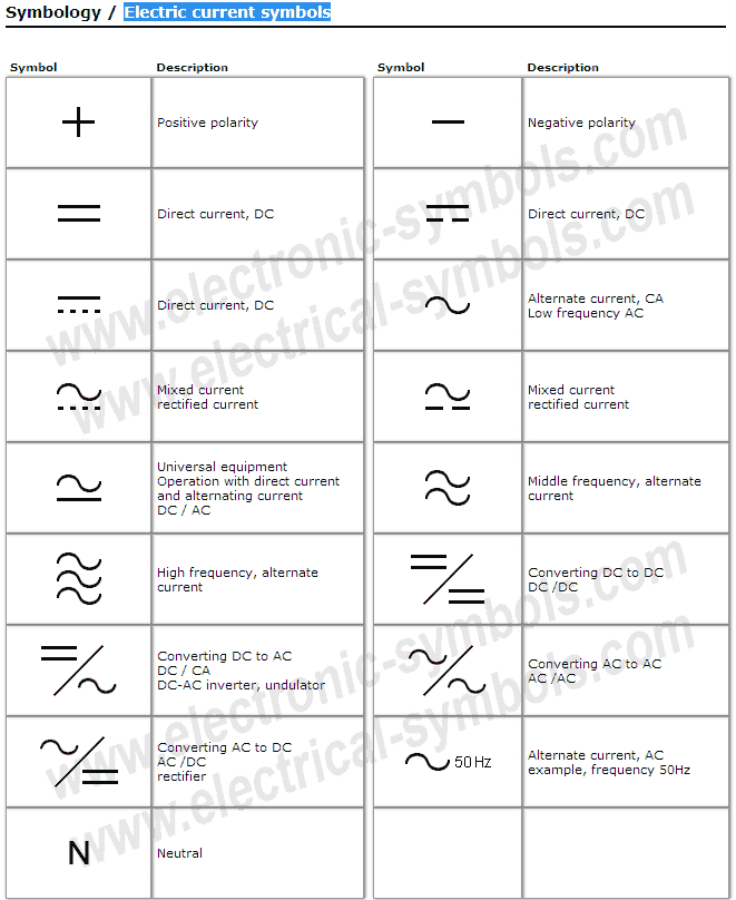
Understanding the meaning behind each symbol is paramount for correctly interpreting electrical diagrams. A seemingly small misinterpretation can have significant consequences, potentially leading to faulty wiring, equipment malfunction, or even safety hazards. Therefore, accurate descriptions accompanying the symbols are just as vital as the symbols themselves. These descriptions typically include information about the component's function, ratings, and connections.
The importance of clear and concise electrical symbols and descriptions extends beyond the design phase. They are essential for troubleshooting, maintenance, and repair of electrical systems. A technician armed with a well-annotated diagram can quickly identify faulty components and implement the necessary repairs. This not only saves time and resources but also contributes to a safer working environment.
The history of electrical symbols is closely tied to the development of electrical technology itself. As new components and systems were invented, corresponding symbols were created to represent them. Over time, these symbols have evolved and been standardized by organizations like the IEEE (Institute of Electrical and Electronics Engineers) and IEC (International Electrotechnical Commission), ensuring global consistency.
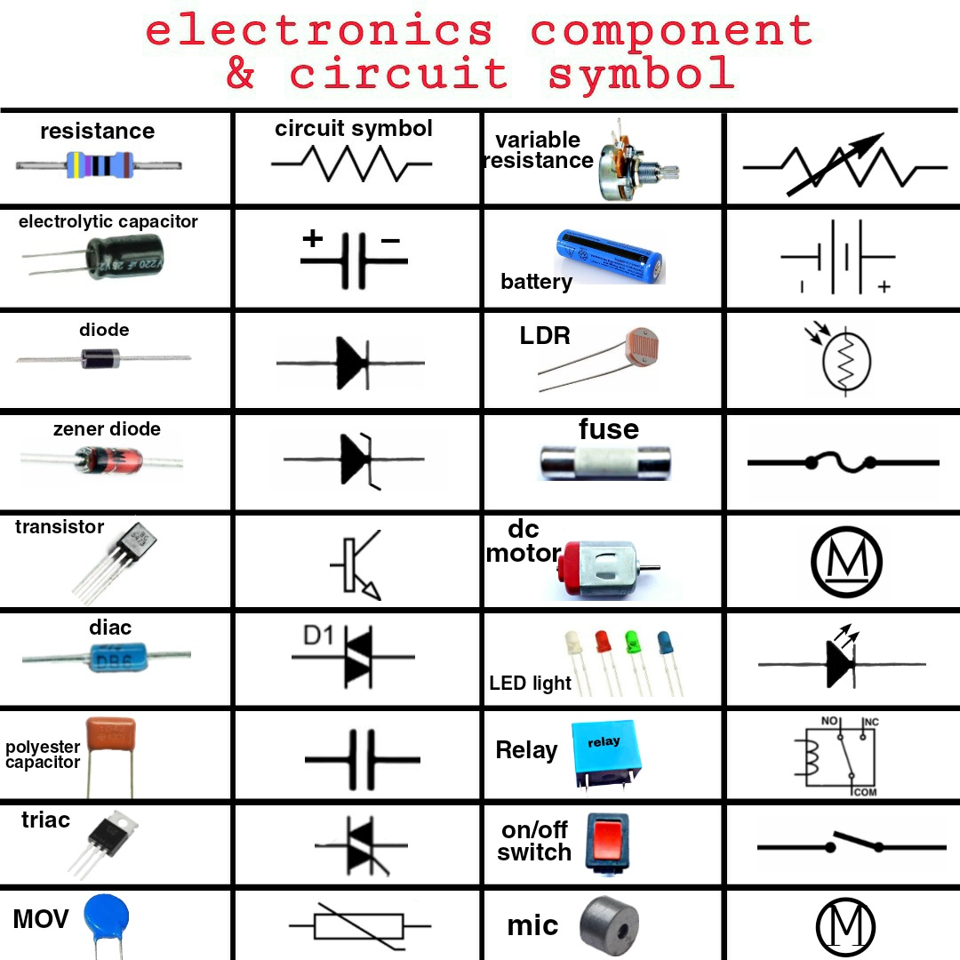
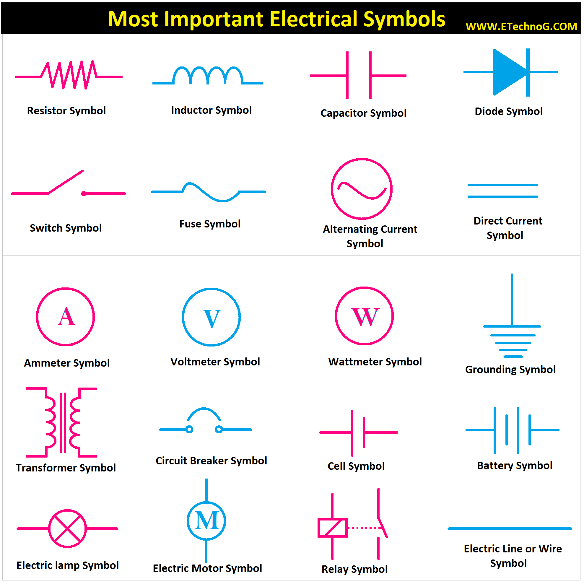
For example, a simple switch is represented by a line with a break in it, indicating its ability to open and close the circuit. A resistor, which impedes the flow of current, is depicted as a zigzag line. These simple yet effective symbols convey crucial information about the components' function.
Benefits of using electrical symbols and descriptions include: improved communication, enhanced safety, efficient troubleshooting, and simplified documentation. Using standardized symbols eliminates ambiguity, ensures clear communication between different stakeholders, and minimizes the risk of errors. Detailed descriptions further enhance clarity, providing specific information about each component's characteristics and connections.
An action plan for effectively utilizing electrical symbols and descriptions might involve: familiarizing oneself with common symbols, practicing reading and interpreting diagrams, and consulting relevant resources like industry standards and textbooks. Regular practice is crucial for solidifying one's understanding and developing proficiency in using these tools.
Advantages and Disadvantages of Standardized Electrical Symbols
| Advantages | Disadvantages |
|---|---|
| Clear and concise communication | Requires learning and memorization |
| Improved safety | Can be complex for very large systems |
| Efficient troubleshooting | Subject to occasional revisions and updates |
Five best practices for implementing electrical symbols and descriptions include: adhering to industry standards, providing clear and concise descriptions, using consistent symbology throughout a project, ensuring legibility of diagrams, and keeping diagrams up-to-date.
Five real examples of electrical symbols include: the symbol for a resistor, a capacitor, a diode, a transistor, and a ground connection. Each of these symbols conveys specific information about the component's function and characteristics.
Five challenges related to electrical symbols and descriptions include: keeping up with evolving standards, dealing with variations in regional practices, interpreting complex diagrams, accurately describing complex components, and ensuring consistency across different design tools. Solutions to these challenges involve continuous learning, consulting with experts, utilizing specialized software, and implementing robust quality control processes.
Frequently Asked Questions about electrical symbols and their descriptions:
1. Where can I find a comprehensive list of electrical symbols? (Answer: Industry standards like IEEE and IEC provide comprehensive lists.)
2. How often are electrical symbols updated? (Answer: Standards are periodically reviewed and updated to reflect advancements in technology.)
3. Are electrical symbols the same worldwide? (Answer: While there is significant standardization, some regional variations may exist.)
4. What resources can I use to learn more about electrical symbols? (Answer: Textbooks, online tutorials, and industry training courses are excellent resources.)
5. How can I improve my ability to read and interpret electrical diagrams? (Answer: Regular practice and consulting with experienced professionals are key.)
6. What are some common mistakes to avoid when using electrical symbols? (Answer: Using incorrect symbols, inconsistent symbology, and unclear descriptions.)
7. How important is it to adhere to industry standards for electrical symbols? (Answer: Adherence to standards ensures clarity, safety, and interoperability.)
8. What software tools are available for creating and managing electrical diagrams? (Answer: Various CAD and schematic capture software tools are available.)Tips and tricks for working with electrical symbols include: utilizing online symbol libraries, creating custom symbol libraries for specific projects, and using software tools with built-in symbol checking features.
In conclusion, mastering electrical symbols and their descriptions is fundamental for anyone working with electrical systems. These symbolic representations provide a concise and standardized way to communicate complex information about circuits and components. From design and analysis to troubleshooting and maintenance, electrical symbols play a crucial role in ensuring the safety, efficiency, and reliability of electrical systems. Understanding their history, importance, and best practices empowers professionals to interpret diagrams accurately, minimize errors, and contribute to the successful implementation of electrical projects. By embracing continuous learning and utilizing available resources, individuals can stay up-to-date with evolving standards and best practices, further enhancing their skills and knowledge in this essential domain. Invest time in learning these symbols – it’s an investment in your professional development and a crucial step towards safer and more efficient electrical work.
Patient communication crafting effective patient follow up messages
Sweet celebrations birthday cakes for a girls 12th birthday
Understanding wells fargo check limits
Electric Circuit Diagram Symbol And Function - You're The Only One I've Told
Circuit symbols with description - You're The Only One I've Told
Electrical Symbols Australian Standard - You're The Only One I've Told
Decoding the Language of Electric Circuit Schematic Symbols - You're The Only One I've Told
Most Common Schematic Symbols On Job Tests - You're The Only One I've Told
Símbolos Electrónicos Electric current symbols - You're The Only One I've Told
Qué significa una flecha doble en un esquema - You're The Only One I've Told
electrical symbols and description - You're The Only One I've Told
Electrical Symbols in PDF for Free Download - You're The Only One I've Told
Electronic Schematic Symbols Chart - You're The Only One I've Told
European Electrical Symbols Chart - You're The Only One I've Told
Basic Electrical Schematic Symbols - You're The Only One I've Told
Common Electrical Symbols With Description - You're The Only One I've Told
Electrical Wiring Diagram Legend - You're The Only One I've Told
Label The Devices In The Circuit Diagram - You're The Only One I've Told


